
Device Configuration
Device Configuration (Adding and Managing Devices)
In Wise SCADA, while the Network represents the communication gateway on your computer, the Device represents the physical hardware accessed through that gateway.
1. Steps to Add a Device
- Go to the Network / Device Hierarchy panel in the top left.
- Find the protocol driver you want to add a device to (e.g., Fulmatic TCP under [1] Network).
- Click the [+] New row immediately below the protocol name.
- This action will add a new device (e.g., [2] Device (2)) to the tree view.
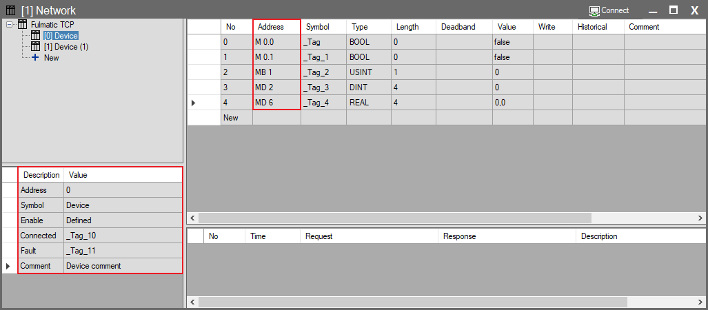
- Select the newly added device and configure the “Address” (Station Address) information in the Device Properties panel at the bottom left to match the address of the physical PLC you want to connect to.
2. Device Properties
- When you select an added device, settings specific to that device open in the bottom left.
- The Address and other communication settings in this panel vary depending on the selected protocol (Modbus, Siemens, Omron, etc.).
- Refer to the Protocol Guides section for protocol-specific details. The table below explains Fulmatic TCP parameters as an example.
| Parameter | Description |
| Address | Station Address: The device’s ID number within the protocol. • Modbus RTU: Slave ID (1-247). • TCP/IP: Usually 0 or Unit ID. |
| Symbol | The symbolic name you assign to the device (e.g., Kiln_PLC, Compressor_2). |
| Enable | Used to activate/deactivate the device’s communication. • When clicked, you can define a Condition from the pop-up window. • Example: Only communicate with this device when the “System_On” tag is True. (If left empty, the device is always active). |
| Connected | The tag bound to this field becomes True when a physical connection is established with the device. (Status monitoring). |
| Fault | The tag bound to this field becomes True if communication is lost or an error occurs. |
| Comment | An explanatory note regarding the device. |
3. Adding and Defining Tags
When you select a protocol (Internal or External) in the tree structure, the tag list for that protocol opens in the right panel. This is where you define all data points your SCADA system will use.
- Adding a New Tag
- You can create a new tag by clicking the + New row at the bottom of the list.
- Meaning of Parameters
- Most columns in this panel (Symbol, Type, Value, etc.) are common for all tag types. However, the Address column carries a different meaning depending on the tag type:
- For Internal Tags
- The Address column specifies the virtual group the tag belongs to (e.g., System, Internal).
- Mathematical operations (.SCALE, .DIV) or bit access (.BIT) are also defined here.
- For External (Power) Tags
- The Address column specifies the physical memory address in the target device (PLC) (e.g., M 0.0, 40001).
- The format of this address changes based on the selected driver (Modbus, Siemens, etc.).
4. Tag List View (Differences)
The tag list in the right panel displays a different Address format depending on what you select in the tree (Network or Device). This is to prevent addressing confusion.
- When Network is Selected: Tags of all devices are listed. Addresses are written with the Full Path to show which device the tag belongs to.
- Example: Device.M 0.0, Device(1).MD 10
- When Device is Selected: Only tags belonging to that device are listed. Since the system already knows which device you are on, addresses are simplified.
- Example: M 0.0, MD 10
5. Communication Status and Log (Bottom Panel)
The log panel at the very bottom of the screen is filtered based on the selection made in the tree.
- If you select a Device; instead of general network traffic, you only see the Request and Response packets exchanged with that specific device.
- This feature allows you to monitor the problematic device without getting lost in the traffic of other devices when performing Troubleshooting on networks with multiple devices.