
Screen Editor
Screen Editor
This interface is the main design environment that appears when you open a Screen from the Project Tree or create a new one. The screens that operators will see in Runtime are created here.
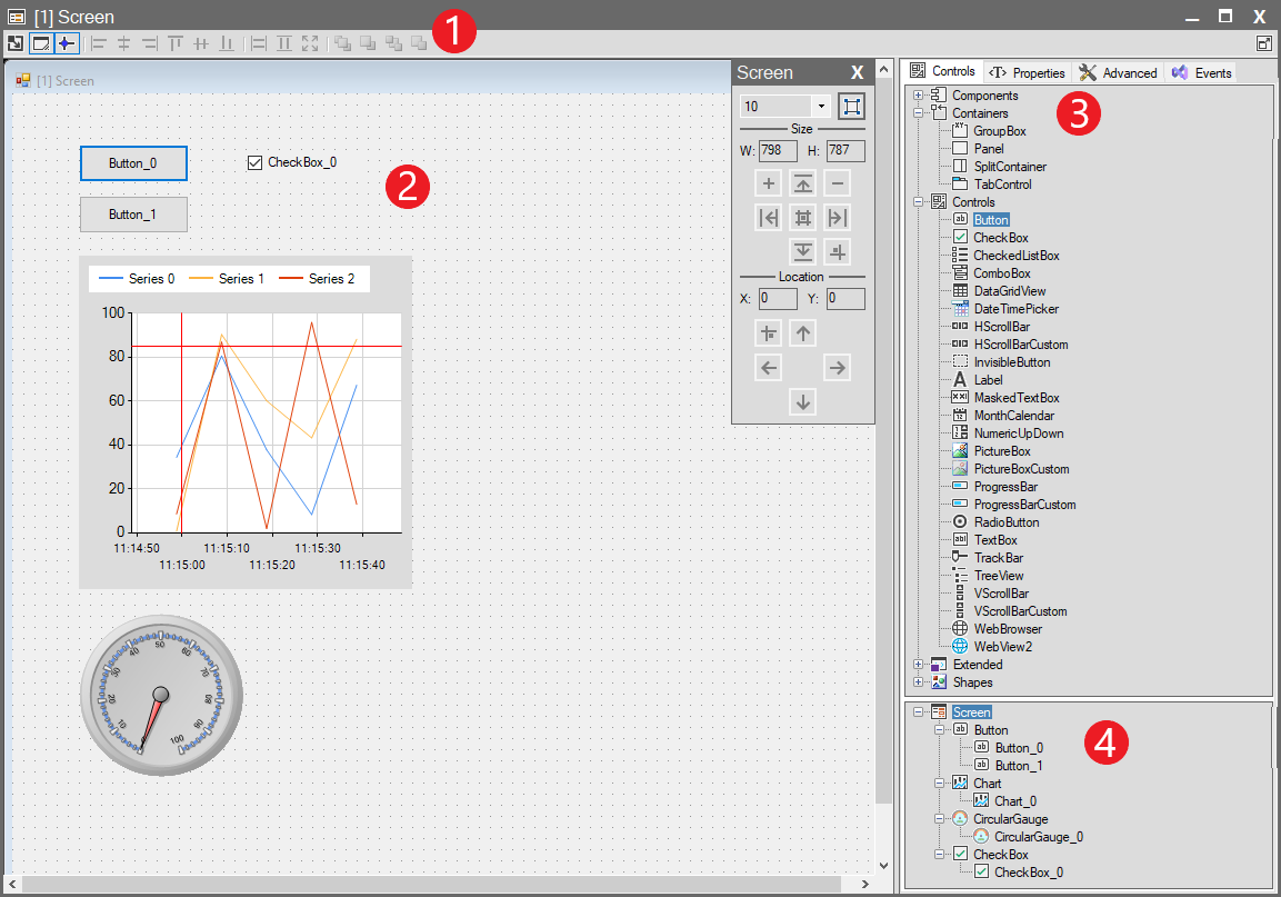
The interface consists of 4 main sections:
1. Screen Toolbar
Includes tools for object alignment (left, right, center), equal sizing (width, height), rescaling, and layer ordering (bring to front, send to back).
For detailed information, see: Screen Toolbar
2. Designer Area
This is the large, gridded area located in the center of the interface. This is your “canvas”. It is the place where you place, resize, and position all visual objects—such as Buttons, Charts, or Circular Gauges—that you drag from the “Controls” panel.
3. Properties and Controls Panel
This is the main panel group located on the right side of the interface where all configurations are made. This panel contains multiple tabs:
- Controls (Toolbox): Your toolbox listing all available objects you can add to the screen. Objects are dragged from here onto the design area.
- Properties / Advanced / Events (Configuration Tabs): Tabs that allow you to configure an object when you select it in the design area.
- Properties: Sets the object’s dynamic (tag-bound) SCADA properties. (See: Properties Panel)
- Advanced: Sets the object’s static (default) .NET properties. (See: Advenced Panel)
- Events: Assigns actions to object events, such as “Click”.
4. Screen Object Tree (Objects Used in Designer Area)
Provides a tree-structure list of all objects present in the design area (Button_0, Button_1, Chart_0, CircularGauge_0, etc.). This list is used to easily select overlapping or hidden objects or to understand the general structure of the screen.